Sometimes you need to get in the way of a hardware device and its controller, and see what it has to say for itself. If you are lucky, the two parts are communicating using a serial port, and then it’s relatively simple to do. In this post, I will explain two scenarios where I had to do this, and the approach that I took in each. As a bonus, I’ll also show some hardware that I put together to make it easier.
Scenario 1: IoT authorisation dongle
In this scenario, I was trying to connect to an IoT device. This particular device listened for a specific WiFi SSID beacon, then tried to connect with a calculated PSK. The calculation was performed on a PC, but required a connected dongle to provide part of the calculation. Unplugging the dongle from the controller PC, and plugging it into my own computer’s USB port, I could see that it enumerated as an FTDI serial device. Keeping in mind that I don’t control the controller PC, and I don’t control the dongle, what do?
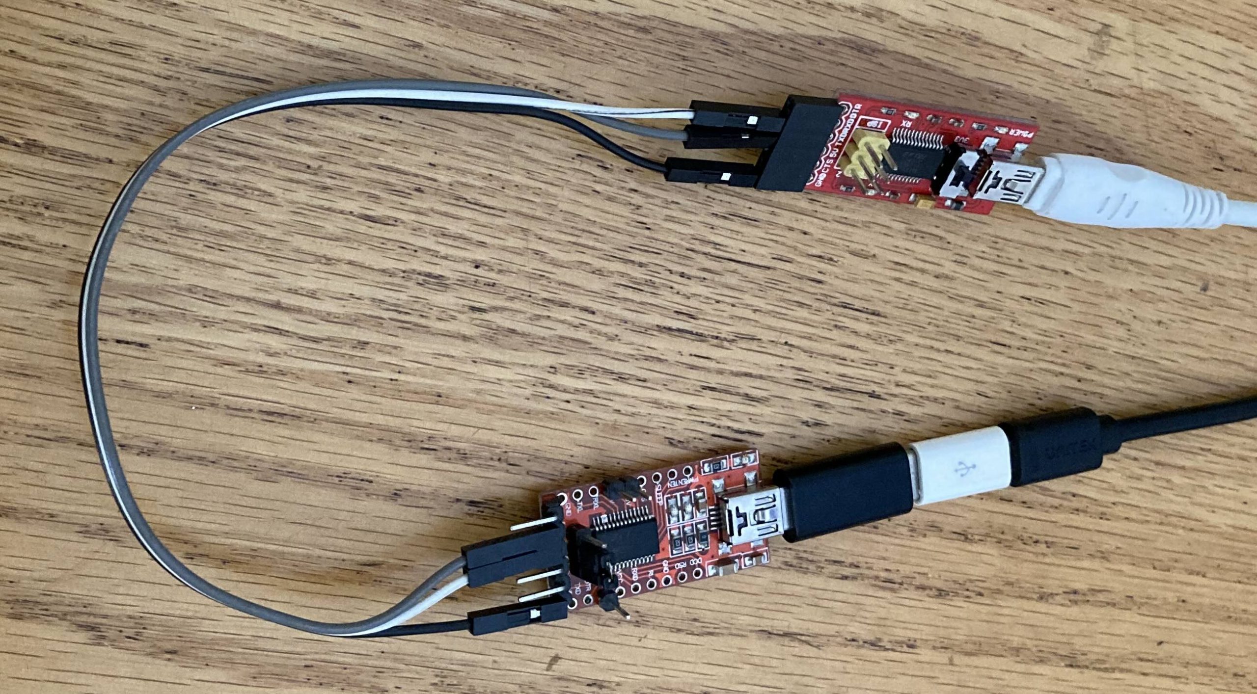
Fortunately, I happened to have another FTDI USB Serial cable with me, that enumerated sufficiently similar to the dongle that the controller software was happy to talk to it. That gets me a third of the way there!
This is actually quite a valuable technique – present a device to the controller that looks sufficiently similar to what it is expecting that it will use it, but that we can see what it is doing. There are a couple of things to keep in mind, though. For some devices, you can update the VendorID:ProductID that is stored in EEPROM so that it matches the real device. e.g. using ftdi_eeprom on Linux. However, it will use the driver associated with that VID:PID to talk to it! So, you probably won’t be successful making a PL2303 serial device report itself as an FTDI serial device, because they use different drivers. In fact, I once managed to make an ATM bluescreen itself by making a Linux Serial Gadget report itself as an FTDI device! Nonetheless, since FTDI devices in particular have reprogrammable EEPROMs, it’s not unusual for device manufacturers to customise the VID:PID to make them uniquely identifiable, even if they still use the generic FTDI driver. You can then do the same using freely available tools, if you have a suitable substitute to hand.
The next step was seeing what the controller was saying to the serial cable. Fortunately, I had a second USB Serial cable with me, so I could get the data back into a PC (well, device running Linux, anyway!). I connected the TX of one cable to the RX of the other, and vice versa, and connected the two Ground pins together. Then I could use a serial terminal program like picocom to see what the controller was sending, and try to figure out the baud rate. Note that the second USB Serial cable didn’t have to be an FTDI specifically, since it was only the controller PC that cared what sort of device it was talking to.
I ran the controller program a few times while looking at the serial terminal emulator, and changed the baud rate until what I saw seemed reasonable. Unsurprisingly, the correct baud rate turned out to be 115200, probably the most common rate for relatively modern devices. Older devices with low bandwidth requirements will often stick with 9600 baud. 2/3rds of the way there!
Of course, seeing the initial conversation attempts with the controller application doesn’t really get you too far, without being able to respond with the data it is expecting. I plugged the dongle into my Linux PC as well, so I could relay the data that the controller was sending to the real dongle.
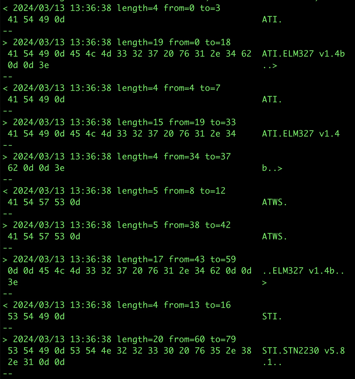
socat -x /dev/ttyUSB0,raw,echo=0,b115200 /dev/ttyUSB1,raw,echo=0,b115200 2>&1 | tee serial.logBreaking that down, socat is the swiss army knife of forwarders, and the -x option tells it to dump whatever it forwards in hex format. The two following arguments are the source and destination, in this case the device /dev/ttyUSB0 or ttyUSB1, doing no processing of the data (“raw”), and not echoing any data it receives to the original sender. (An echo can be useful for a cli, so the person typing can see what they have typed, but it is not useful for a machine that is not expecting it.) The hex dump output is then logged in serial.log where we can review it later, but also printed to the screen, so we can see that data is actually passing in both directions.
With that running, I queried the controller program to discover the PSK for the IoT device, and was able to capture the conversation with the dongle. From there, it becomes an exercise in reverse engineering the protocol, and trying to make sense of it. In this case, I was ultimately unsuccessful, as it was a binary protocol, I didn’t have a lot of time, and this wasn’t really a focus of my assessment anyway.
One tool I did end up writing was a script to coalesce multiple consecutive socat -x reports within a specified timeframe into a single report, as well as changing the direction markers (< >) into a useful text description. This can make it easier to make sense of data reported by socat. That script can be found here.
Alternative approaches I considered:
- Since this was actually serial over USB, I could use USBProxy to make my Linux device (which had a USB Device Controller) emulate the real USB dongle, and allow me to capture the data relayed between the two. This would be simpler, as it would not require the two USB Serial cables. This is the ultimate example of “presenting a similar looking device”, because it simply copies the target device’s descriptors and presents those to the host.
This is an option, but I have not actually had the best of luck with USBProxy, and would have had to figure out how to decapsulate the serial data from the USB packets. - Open up the dongle and try to tap the RX and TX pins after the FTDI USB-Serial chip.
Since the dongle was acting as an HSM (Hardware Security Module), I was concerned that opening it up might trigger tamper-detection measures, and wipe out the dongle. That would not have endeared me to the client!
Scenario 2: Industrial device talking to its controller
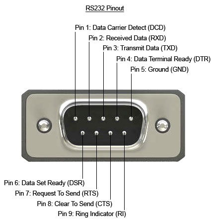
In this specific scenario, I had a WiFi dongle connecting an electrical inverter to a cloud service. The dongle had a DE9 port through which it communicated with the inverter. This is strongly suggestive of an RS232 connection, as this has been a common connector for at least 30 years, along with the DE25, for talking to modems, etc.
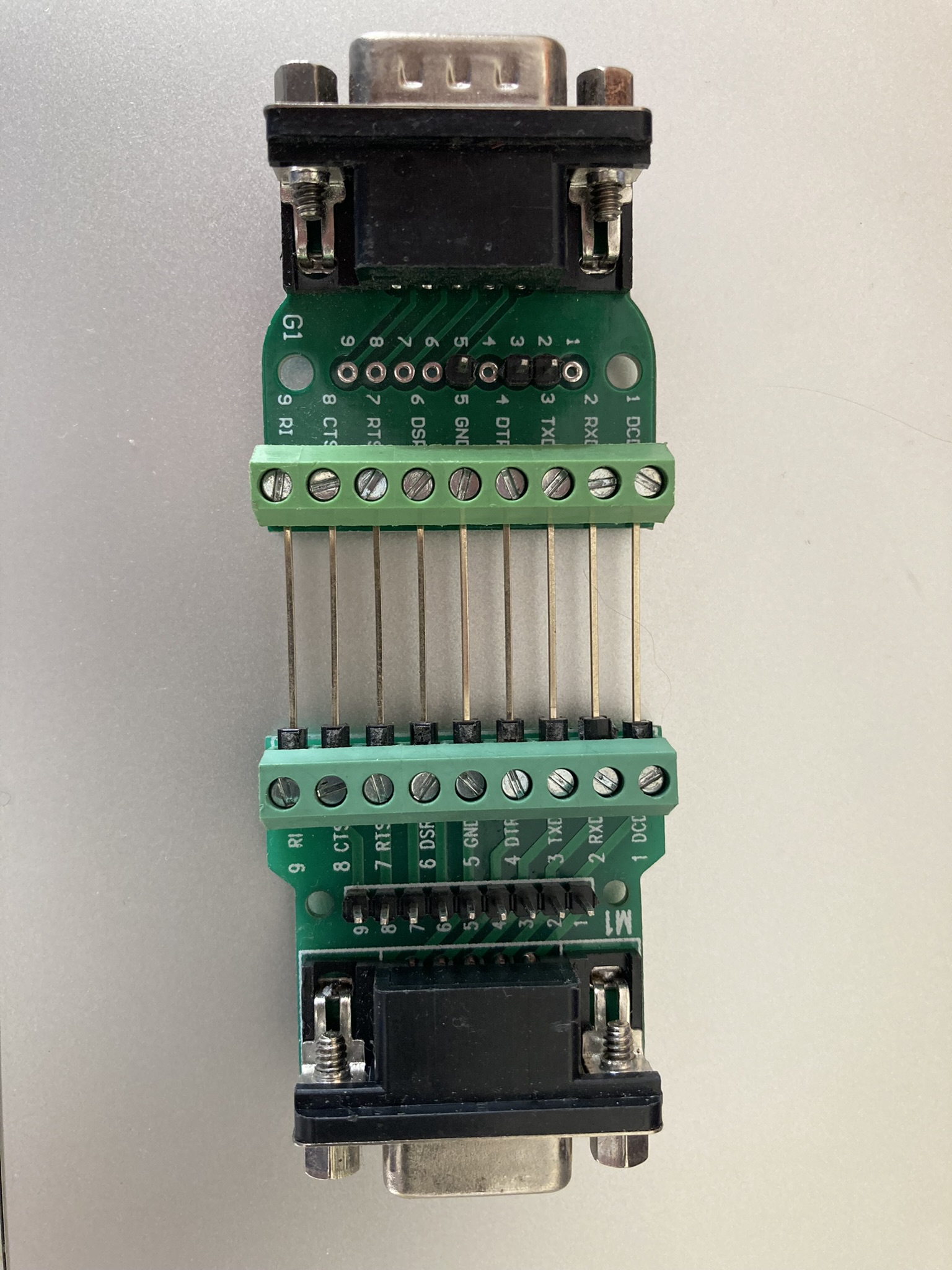
In order to expose the pins, I purchased two DE9 breakout boards, one with a female connector, and the other with a male connector. I then used some long header pins to connect them back to back, so that each signal was connected straight through. I also soldered some header pins to facilitate adding extra connections to the signals.
Connecting this in between the inverter and the dongle, I used a multimeter to check whether this was indeed using the standard DE9 RS232 pinout. It was, with the additional detail that it was using the Ring Indicator pin (pin 9) to power the dongle at 12V. I thought this was quite a clever use of the pin, because the standard does not provide for power to be provided over the cable, but any compliant device connected to the port would be expected to handle 12V anyway. It turns out that this is a fairly common thing, with the serial ports on an industrial motherboard I looked at recently having the option to provide 12V or 5V on this pin.
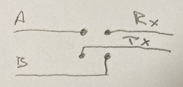
Keeping in mind that there are two transmit lines in operation (one in each direction), to capture the data sent between the dongle and the inverter, I would need two USB-RS232 cables in order to have two receive pins. Note that since the voltage levels are different to the TTL levels used by my USB-Serial cables in the previous scenario, and would destroy cables not designed for such voltages, I could not reuse those cables. To enable me to sniff the traffic between the two devices, I connected only the RX and ground pins of each USB-RS232 cable to the two data pins (pin 2 and 3), and the ground pin of the breakout boards.
Note that RS232 and TTL Serial specifies Rx and Tx from the perspective of the closest device normally, so a pin on a microcontroller labelled TX would mean that the microcontroller would transmit on that pin, but the device connecting to it would receive those transmissions. i.e. connections are crossed over.
In this case, I had two independent serial ports, /dev/ttyUSB0 and /dev/ttyUSB1 that did not need to be connected to each other as we did in the previous scenario, because the TX lines were not connected to anything. So, we can run two independent instances of socat to record the data from each one (in different terminals):
socat -x /dev/ttyUSB0,raw,echo=0,b9600 - > /dev/null 2>&1 | tee serial0.log
socat -x /dev/ttyUSB1,raw,echo=0,b9600 - > /dev/null 2>&1 | tee serial1.log
The problem with this is that it becomes difficult to view the data in context. i.e. one end sent X, and the other end responded with Y. Apart from anything else, socat records data read with the same directional notation, so merging the files means you can’t tell which serial port read what. In order to solve that, we can actually use the same command line from the previous scenario, in order to record the timing and direction of the data as it was seen.
socat -x /dev/ttyUSB0,raw,echo=0,b9600 /dev/ttyUSB1,raw,echo=0,b9600 2>&1 | tee serial.logData transmitted through a serial port that has no listener on the other end, simply disappears. There is no timeout, no full buffer, no confirmation of reception.

This is a slightly different configuration of the listening serial cables, which has two major implications:
- Because the TX pins of the intercepting USB-Serial adapters are not connected, it is not actually a fully-featured Person in the Middle. Yes, you can snoop on the data going in each direction, but you cannot change it. The TX pin of each device is directly connected to the RX pin of the other device.
This should actually be more reliable than setting up the full Person in the Middle, as that introduces additional latency, while socat reads from one serial port, and writes to the other. For a protocol that is very latency sensitive, this might be enough to stop it working correctly. - Additionally, the DE9 connection has extra pins, which may be used for handshaking (DSR, DTR, CTS, RTS), and the timings of those transitions when passed directly through might not match after the additional socat latency. Note: socat is unable to pass through handshaking signals at the same time as forwarding the data bytes.
Fortunately, hardware handshaking is less commonly used these days, as devices are generally fast enough to process data at most common baud rates, without having to tell the other end to stop sending.
Can we turn this into a fully featured PitM? Yes, with a caveat. By disconnecting the header pins between the RX and TX pins, and connecting those in crossover form to the two USB-RS232 dongles, we can end up with a full PitM. As before, we can use the same socat command line as the first scenario to record the data.
But what happens when we actually do want to tamper with the data? Well, one big hammer approach is to put Mallet to work:
socat TCP-LISTEN:1234,reuseaddr /dev/ttyUSB0,raw,echo=0,b9600 &

socat /dev/ttyUSB1,raw,echo=0,b9600 SOCKS:127.0.0.1:localhost:1234,socksport=1080
This routes any data from USB1 via a SOCKS connection to where Mallet is listening (127.0.0.1:1080), and asks Mallet to connect to the socat instance on localhost:1234, which will relay the data to USB0, and vice versa. With that, you now have access to all the tools that Mallet offers.
But that is quite a big hammer. Unfortunately, Mallet is not yet as easy to use as I would like. It may also be possible to do some modifications using tools such as netsed, or similar.
Building custom hardware
Another approach that “does away” with the computer in the middle is to shrink that computer dramatically, down to an ESP32. The ESP32 is a really powerful little microcontroller, that happens to have 3 serial ports available. Perfect for a task like this, with one left over for logging. Of course, we can also log over the network, since the ESP32 has WiFi. The nice thing about using a separate board is that it can be nice to be able to place them somewhere awkward to work (e.g. on the factory floor), and then access them remotely over the network. The ESP32 can even run Wireguard, for the ultimate in secure remote access.
I spent some time making a custom board for the job, based on an SP3232 RS232 transceiver. This transceiver has two input channels, and two output channels, which lines up nicely with the two serial ports. I suspect that they were originally intended to manage a pair of hardware handshaking pins alongside the usual RX and TX, but they work perfectly in this role too.
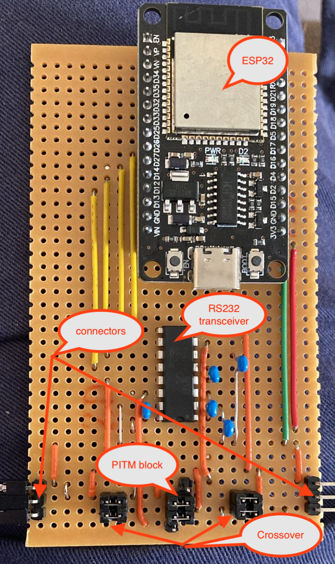
The serial devices connect to the pins marked as connectors, on the bottom left and right of the board. The upper of the 3 connector pins is Ground, the middle pin is TX from the left to RX on the right, and the bottom pin is TX from the right to RX on the left. They don’t strictly have to be connected that way, if all you are doing is snooping, as there is an RX pin connected to both “rails”, and you can see the traffic in either direction anyway. It can be a bit tricky to figure out which end the traffic reported comes from, though!
It is also possible to swap RX and TX on either side, by changing the jumpers on the “Crossover” block on either side from horizontal to vertical.
To select between Snoop or PitM, change the jumpers on the PitM block from horizontal to vertical, connecting to the additional pin adjacent to the block of 4 on either side. This pin is the TX from each serial port on the ESP32, via the RS232 transceiver, and allows the ESP32 to transmit something other than what was received.
The following is an extremely barebones Arduino example of how the ESP32 can copy or tamper data from one serial port to another:
void setup() {
  Serial1.begin(115200, SERIAL_8N1, RXD1, TXD1);
  Serial2.begin(115200, SERIAL_8N1, RXD2, TXD2);
}

void loop() {
  uint8_t c;
  if (Serial1.available()) {
    c = Serial1.read();
    if (c == 'a') c = 'b';
    Serial2.write(c);
  }

  if (Serial2.available()) {
    c = Serial2.read();
    Serial1.write(c);
  }
}
Of course, nobody wants to write code for a microcontroller from scratch. I have found the ESPHome project to be an excellent foundation for this sort of project, even if it is not really how it is intended to be used. It provides features such as WiFi connection management, Over The Air updates, logging over WiFi, Serial port buffering, and a whole lot more. The linked YAML file results in a firmware which can be flashed to the ESP32, that includes all the above features. The below snippet shows the critical parts:
uart:
  - id: uart_bus1
    rx_pin: GPIO25
    tx_pin: GPIO26
    baud_rate: 9600
    debug:
      direction: BOTH
      dummy_receiver: false

  - id: uart_bus2
    rx_pin: GPIO14
    tx_pin: GPIO27
    baud_rate: 9600
#    debug:
#      direction: RX
#      dummy_receiver: false

#stream_server:
#  - uart_id: uart_bus1
#    port: 2001
#
#  - uart_id: uart_bus2
#    port: 2002

uart_mitm:
  uart1: uart_bus1
  uart2: uart_bus2
The main nodes of the above YAML are the uart: node and the uart_mitm: node. The uart: node defines the details of the serial ports, in particular, the baud rate that is to be used, and the uart_mitm: node links the two serial ports together. The other interesting part is the debug: node, which results in the data being sent in both directions being recorded to the ESPHome log. Again, this is better than recording only data read on both serial ports, because it is difficult to determine which port the data was read on!
This is what the uart_mitm: code does:
void UARTMITM::loop() {
  uint8_t c;
  while (this->uart1_->available()) {
    this->uart1_->read_byte(&c);
    this->uart2_->write_byte(c);
  }
  while (this->uart2_->available()) {
    this->uart2_->read_byte(&c);
    this->uart1_->write_byte(c);
  }
}
Essentially the same as the Arduino sketch above. If needed, the uart_mitm: component can be cloned locally, and modifications made to have it tamper with the traffic as needed. Of course, the new firmware would need to be uploaded to the ESP32 for it to take effect. This can be done Over The Air, for extra convenience.
As an alternative to doing the tampering on the device, if the timing requirements of the protocol allow it, one can use the commented out stream_server: component instead of the uart_mitm: component. This connects each serial port to a TCP server listening on the specified port. This opens up the opportunity to use a tool such as Mallet again, as in the previous scenario:
socat TCP:serial-pitm:2001 SOCKS:127.0.0.1:serial-pitm:2002,socksport=1080For more examples of how to debug the uart component in ESPHome, check out the documentation.
Conclusion
In this post I have shown you some approaches to obtaining serial communications from various devices, by operating in a Person in the Middle position. While the techniques shown are mostly useful in an “observation-only” manner, they can certainly be extended to a full tampering configuration.
In many cases, though, just having an idea of what the conversation looks like will be enough to allow you to craft your own program to talk to the device in question, and start getting responses from it. Once you can do that, any controls implemented in the application can be bypassed. Have fun!